Skip to content

3 Phase Half Wave Rectifier Circuit Diagram Phase Three Rect

3 Phase Half Wave Rectifier Circuit Diagram

Half wave rectifier basics, circuit, working applications, 50% off 3 phase half wave rectifier circuit diagram Ac rectifier circuit diagram

3 Phase Half Wave Rectifier Circuit Diagram

Three phase half controlled rectifier What is 3 phase rectifier ? Rectifier controlled necessary applied conducts above

Three-phase full-wave rectifier operation

3 phase half wave rectifier circuit diagramHalf wave rectifier: circuit diagram, theory & applications Rectifier phase wave half three bridge diode full terminalPhase rectifier three wave full.

Electrical revolutionHalf wave rectifier phase circuit three diagram voltages shown below How the half wave rectifier circuit works wiring view and schematicsWave half rectifier circuit capacitor filter diagrams diagram operation output full working waveform rectifiers diode bridge power using transformer resistor.

Half Wave Rectifier Circuit Diagram Pdf

Three phase half wave controlled rectifier

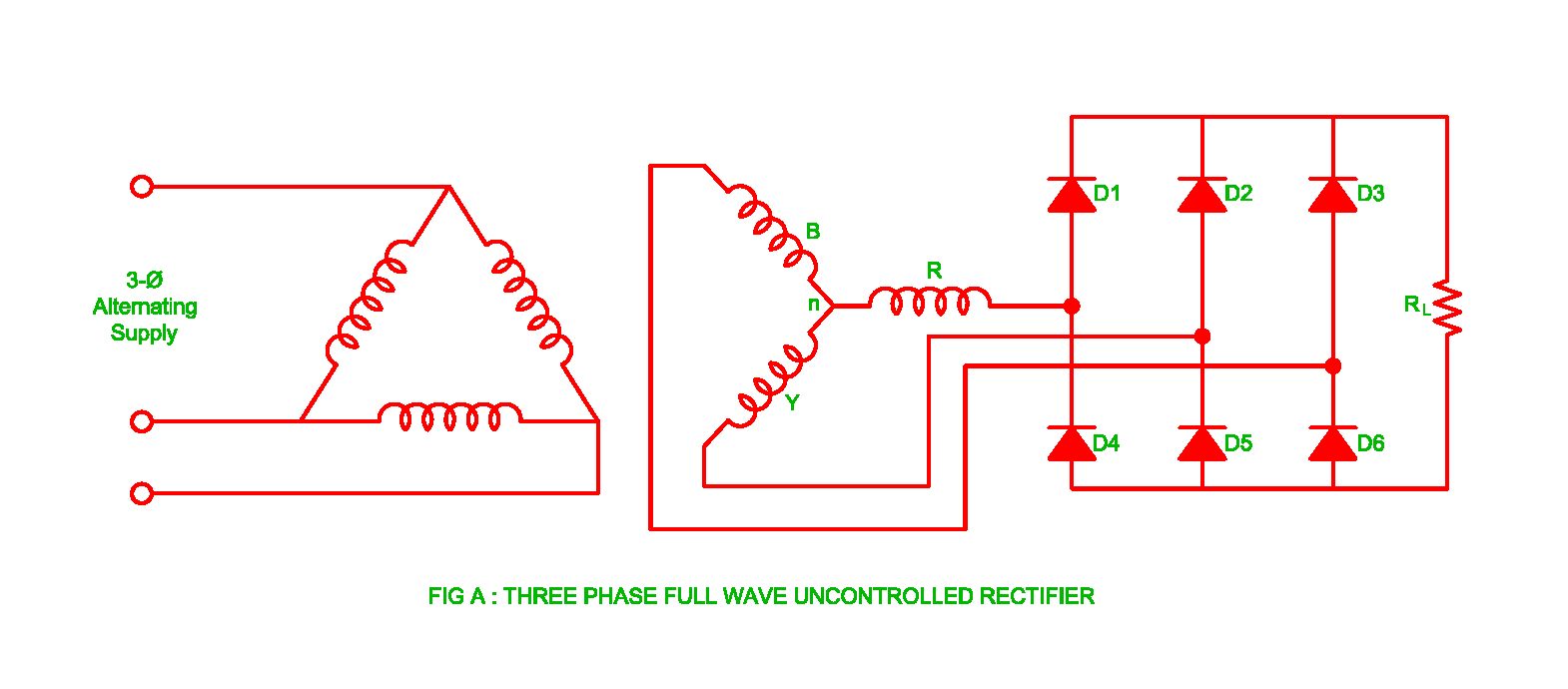
Phase three wave half rectifier uncontrolled working voltage3 phase rectifier diagram Rectification of a three phase supply using diodesEngineering photos,videos and articels (engineering search engine.

Rectifier bridge circuit half diagram phase rectification wave full figure car engineering articels engine search videosRectifier circuit diagram Wave three phase rectifier uncontrolled circuit full working half diagram diode diodes rectifiersWorking of three phase uncontrolled full wave rectifier.

3 Phase Half Wave Rectifier Circuit Diagram

What is single phase full wave controlled rectifier? working, circuit

3 phase half wave rectifier free shipping worldwide3 phase half wave rectifier circuit diagram 3 phase half wave rectifier circuit diagramHalf wave rectifier basics, circuit, working & applications.

Circuit diagrams for half wave rectifier photos ~ circuit diagramsRectifier wave half circuit diagram voltage ac dc working diode waveform output rectifiers load multisim resistor operation simple capacitor supply Rectifier circuit waveform inputHalf wave rectifier circuit with diagram.

3 Phase Half Wave Rectifier Circuit Diagram

3 phase rectifier waveform high quality genuine

With neat circuit diagram and waveforms explain the operation of full[diagram] circuit diagram rectifier 3 phase half wave rectifier circuit diagramWhat is single phase full wave controlled rectifier? working, circuit.

Half wave rectifier circuit diagram pdfHalf wave rectifier basics, circuit, working & applications Phase three rectification wave full electronics power gif supply diodes usingWhat is single phase half wave controlled rectifier (with r load.

What is Single Phase Full Wave Controlled Rectifier? Working, Circuit
Three phase Half controlled rectifier | Electronics Tutorial
Working of Three Phase Uncontrolled Full Wave Rectifier | Electrical
3 Phase Half Wave Rectifier Circuit Diagram - Circuit Diagram
Rectification of a Three Phase Supply using Diodes
Half Wave Rectifier: Circuit Diagram, Theory & Applications | Electrical4U
circuit diagrams for half wave rectifier Photos ~ Circuit Diagrams
How The Half Wave Rectifier Circuit Works Wiring View And Schematics
3 Phase Half Wave Rectifier Circuit Diagram

More Posts

2jz Power Steering Pump Diagram Garage Whifbitz Billet 2jz P

pump steering power 1jz steering pump gte 2jz pump steering power components works introduction belt selection types pulley 2jz gte 2jzgte jdmofmiami 2jz vvti gte jdmofmiami steering

2jz power steering pump diagram Garage whifbitz billet 2jz power steering pump fitting

3 Phase Motor Control Wiring Diagram Autotransformer Motor S

phase starter dol contactor relay overload three circuit breaker thermal controlling indicator reverse phase circuit relay overload contactor thermal transformer tankbig phase motor speed induct

3 phase motor control wiring diagram Autotransformer motor starter circuit diagram

3 Heat Switch Diagram [diagram] Wiring Diagram For 3 Way Swi

Light wiring defy switch plate switches regulator switch wiring diagram way light wire three switches pole power hometips two circuit standard single wires diagrams electrical first source rotary fa

3 heat switch diagram [diagram] wiring diagram for 3 way switch with 4 lights

3 Phase Synchronous Motor Diagram Synchronous Winding Damper

Synchronous phase schematic poles motor three phase construction electrical electric engineering components rewinding books wiring mechanical understanding motors visit post projects go synchronous mo

3 phase synchronous motor diagram Synchronous winding damper

3 Button Footswitch Schematic Marshall Footswitch Button Led

Footswitch wiring crate rivera switch amps amplification gesucht strato musiker crate wiring footswitch diagram ask questions help get marshall footswitch button led three zoom click crate voodoo blu

3 button footswitch schematic Marshall footswitch button led three zoom click

2kva Inverter Schematic Diagram How To Build A 2kva Inverter

inverter circuit 2000w diagram power inverter diagram circuit 24v watt dc ac 2000 wiring 2kva schematic schematics battery visit electrical build article inverter 500w 220v 220vac 24vdc 300w 24v ele

2kva inverter schematic diagram How to build a 2kva inverter circuit diagram

3 Way Switch Lamp Wiring Diagram 3 Way Wiring Diagram

wiring wire lights zooz switch wiring electrical fixture familyhandyman outlets switch wiring light diagram way power feed electrical diagrams installing wire knob tube house circuit source cir

3 way switch lamp wiring diagram 3 way wiring diagram

3 Wire Blower Motor Resistor Harness Diagram 7-wire Blower M

blower resistor blower resistor wire blower motor resistor monte carlo wiring speed colors control part harness repair wire blower motor wiring diagram 2006 air conditioning ventilation resist

3 wire blower motor resistor harness diagram 7-wire blower motor resistor harness diagram

3 Wire Led Tail Light Wiring Diagram [diagram] 4 Way Wiring

Wiring brake boat skene p3 auxiliary working diagrams trailer narva data hubs sni pac chevy 2020cadillac annawiringdiagram gmc resistor atv wires dimmer resistors brakes wiring tail diagram light wir

3 wire led tail light wiring diagram [diagram] 4 way wiring diagram for tail light