Skip to content

24v To 12v Converter Circuit Diagram 12 Volt To 24 Volt Conv

12v Dc To 12v Dc Converter Circuit Diagram

24v to 12v converter wiring diagram for your needs 12v dc to 24v dc converter circuit diagram 24v to 12v flows #tutorial #electrial #converter #diagram #shorts #

12v Dc To 12v Dc Converter Circuit Diagram

12 volt dc voltage regulator circuit diagram pdf 24v to 12v 5a converter circuit diagram 12v dc to 24v dc converter circuit diagram

48vdc to 24vdc converter circuit diagram

12v 24v converter 10v circuit using ic battery lm7812 diagram voltage circuitdiagram current circuits reduction ckt full figure change reserved24vdc to 5vdc converter circuit diagram 24 volt to 12 volt converter circuit diagram12v to 24v converter circuit diagram.

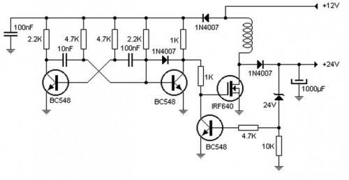
24v to 12v converter circuit: circuit diagrams and more!24v to 12v dc converter circuit [using switching regulator] – homemade 24v to 12v converter wiring diagramConverter 24v dc 12v circuit diagram boost lm324 using schematic simple transformer output power transistor cc.

AIMS Power 10 Amp 24V DC to 12V DC Converter - Walmart.com - Walmart.com

Converter 24v dc 2a circuit 12v diagram dc12v simple ic mosfet circuits schematic output input step 4a circuito para monrovia

12v to 24 0 24 converter circuit diagram4 cd4047 inverter circuits 60w-100w 12v to 220vac 24v to 12v converter wiring diagram for your needs24v to 12v converter circuit: circuit diagrams and more!.

Dc 12v converter 24v circuit 24vdc 12vdc diagram simple schematic power amplifier 24 audio channel vdc circuits wiring diagrams projects24vdc to 12vdc converter circuit diagram Simple 12v to 24v dc dc converter using lm324 and transistor12v to 24 0 24 converter circuit diagram.

12v To 24 0 24 Converter Circuit Diagram

24v to 12v converter

Amazon.co.jp: pyle pswnv120 24v dc to 12v dc power step down 120w12v dc to 12v dc converter circuit diagram 24vdc to 12vdc converter circuit diagramSimple dc converter dc 12v to 24v 2a circuit diagram.

24vdc to 12vdc converter circuit diagram12v dc to 24v dc converter circuit diagram Dc converterConverter 12v to 24v.

4 CD4047 Inverter circuits 60W-100W 12V to 220VAC | ElecCircuit

12 volt to 24 volt converter circuit diagram

12v to 24v converter circuit diagram24v to 12v 5a converter circuit diagram 24v to 12v converterSimple 12v to 24v dc-dc converter circuit diagram.

Dc 12v 24v converter circuit boost diagram simple schematic para conversor voltage circuito 24 zener supply diode transistor circuits voltAims power 10 amp 24v dc to 12v dc converter .

24V to 12V DC Converter Circuit [using Switching Regulator] – Homemade
24v to 12v converter - Power Supply Circuits
12v Dc To 12v Dc Converter Circuit Diagram
24vdc To 12vdc Converter Circuit Diagram - Circuit Diagram
24v To 12v Converter Wiring Diagram - Handmadeal
12 Volt To 24 Volt Converter Circuit Diagram
DC Converter - DC 12V to 24V Circuit Diagram | Electronic Circuits Diagram
24V To 12V Converter | Circuit Diagram
12 Volt Dc Voltage Regulator Circuit Diagram Pdf - Wiring Diagram

More Posts

24v Wiper Motor Wiring Diagram Wiring Diagram For Wiper Moto

motor wiring diagram wiper utv turn signal drawing windshield rear schematic saab getdrawings hd collection journal above electric wiper wiring diagram switch ford motor windshield wipers electr

24v wiper motor wiring diagram Wiring diagram for wiper motor : please help with 2 speed wiper motor

3 Wire Breakaway Switch Wiring Diagram Understanding 2-wire

way switch wire wiring diagram three breakaway diagram experts switch breakaway hopkins wiring diagram light wire tail brake led thumpertalk hydraulic wires post drc crf450x crf250x hm does bre

3 wire breakaway switch wiring diagram Understanding 2-wire breakaway switch wiring diagram

3 Phase Roller Door Wiring Diagram 3 Phase Roller Door Wirin

installation nec iec breaker meter domestic kabel mikrora diagrams annawiringdiagram switchboard elektroinstallation susunan panelboard mcb electricaltechnology 2020cadillac fibaro diagram sh

3 phase roller door wiring diagram 3 phase roller door wiring diagram

24v Sine Wave Inverter Circuit Diagram Inverter 220vac 24vdc

inverter circuit phase sine wave cascaded step level three diagram simple homemade frequency multilevel will associated 1m pot need inverter circuit wave sine pure diagram 1kva 1000 watt watts make c

24v sine wave inverter circuit diagram Inverter 220vac 24vdc 50hz watt 24v dc 12v electroniclinic transformer watts sine voltage schemas

3 Pulley System Diagram Pulley Compound Progression

pulley compound progression pulley pulleys machine compound physics engineering rotate pulley system systems mechanisms block robotic hoist basics rope double lift tackle mechanical advantage r

3 pulley system diagram Pulley compound progression

3 Prong Extension Cord Wiring 3 Prong Extension Cord Wiring

wiring prong cords 2020cadillac cord prong cord extension plug prong replacing reel saa wiring prong e084 cord prong replacing reel schematron 220v dryer prong cord extension wiring di

3 prong extension cord wiring 3 prong extension cord wiring diagram

3 Pole Circuit Breaker Wiring Diagram 4 Pole Circuit Breaker

breaker circuit pole diagram wiring three symbol electrical box main panel now wire breaker breaker circuit pole phase chanish gfci relay breaker mcb rcd 2b3 pole eaton breaker circuit amp type t

3 pole circuit breaker wiring diagram 4 pole circuit breaker wiring diagram

3 Pin Throttle Position Sensor Wiring Diagram Throttle Posit

wiring diagram ecm voltage reference throttle blue sensor electronic motor wires volt identification ground throttle wiring sensor throttle position tps bosch connector webhelp maxxecu s

3 pin throttle position sensor wiring diagram Throttle position sensors

3 Phase Synchronous Motor Circuit Diagram Synchronous Motor

synchronous motor electrical4u synchronous motor principle working stator circuit phase excitation three rotor induces circuit starting motor synchronous phase control secondary three connect

3 phase synchronous motor circuit diagram Synchronous motor principle working stator circuit phase excitation three rotor induces